Dig Pod 1 has a servo at every joint, and a servo has to keep drawing current to hold a load. I wondered whether a lead screw could hold the arm instead, so I built that arm in Bench before printing anything. Nothing is printed and I haven't measured a single watt. What the virtual build did give me is a list of things to look at first, and a few mistakes I made in the sandbox instead of on the printer.
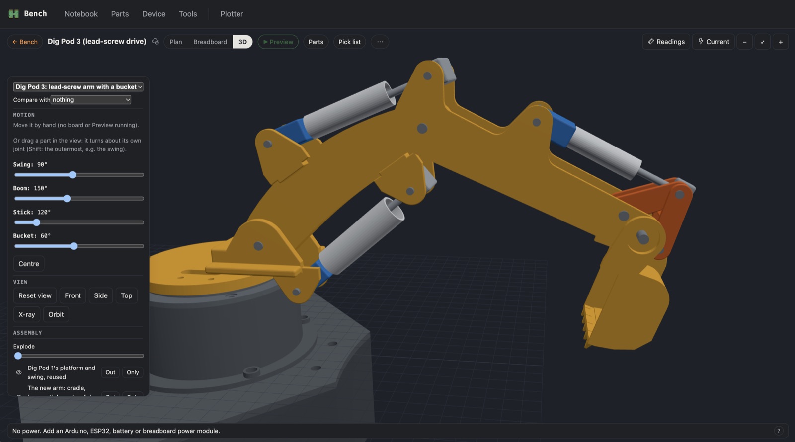
Why look for an alternative
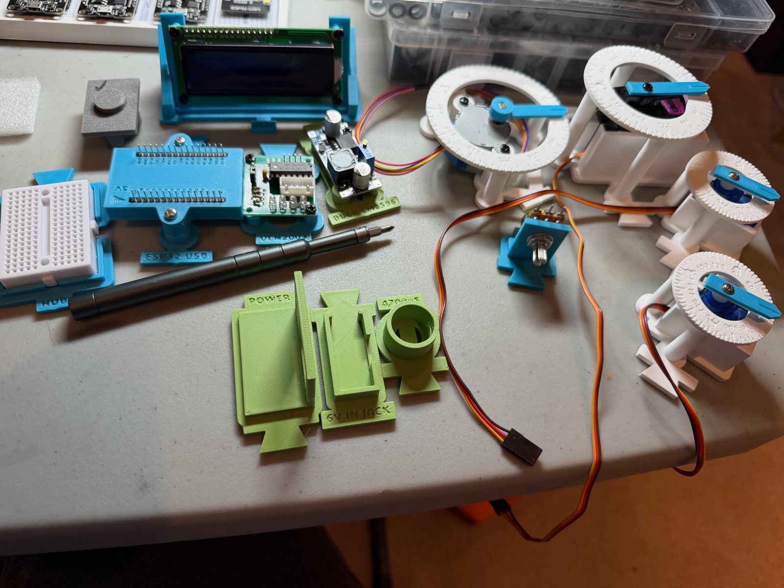
The first Dig Pod has an MG996R on the boom and SG90s on the stick and bucket. A servo holds a load by pushing against it all the time, so it draws current even when the arm stands still. On my bench the stick's SG90 buzzed at every position, and once it pulled the 2 A charger down until the rail read 3.14 V. I already suspected it was too small. Claude worked out by how much: it added up the weight of every printed link, the servos and a scoop of lentils, and took the gravity load about each joint.
| Joint | Servo now | Worst load, empty to full scoop (kg·cm) | Servo's stall rating |
|---|---|---|---|
| Boom | MG996R | 1.8 to 4.0 | 11 |
| Stick | SG90 | 0.6 to 1.9 | 1.8 |
| Bucket | SG90 | 0.05 to 0.3 | 1.8 |
That's gravity only, with no digging force. A servo shouldn't sit above a third to a half of its stall rating, so the stick is the problem, and the fix is either a bigger servo or a different way to hold the arm.
The idea from YouTube
I watched a few toy excavator builds. They drive the arm with a small servo at the end of a white tube, turning a threaded rod or a coil spring with a nut running along it. That could help in three ways. A fine screw doesn't back-drive, so it can hold a load with the motor switched off. The cylinder pushes from an offset pin, which gives leverage. And a screw turns a small torque into a big push: back of the envelope, a 1.8 kg·cm servo on a 2 mm lead at 30 % efficiency pushes about 170 N. That efficiency is a guess, not a measurement.
It has catches I wouldn't have seen without drawing it. A standard SG90 only turns 180°, so those builds must use continuous-rotation servos, which have speed and direction but no position, and my arm's collision guard needs the angles. A drill bit looks like a lead screw, but its flute is so steep that it back-drives, so it would be fast and wouldn't hold.
Bench to the rescue
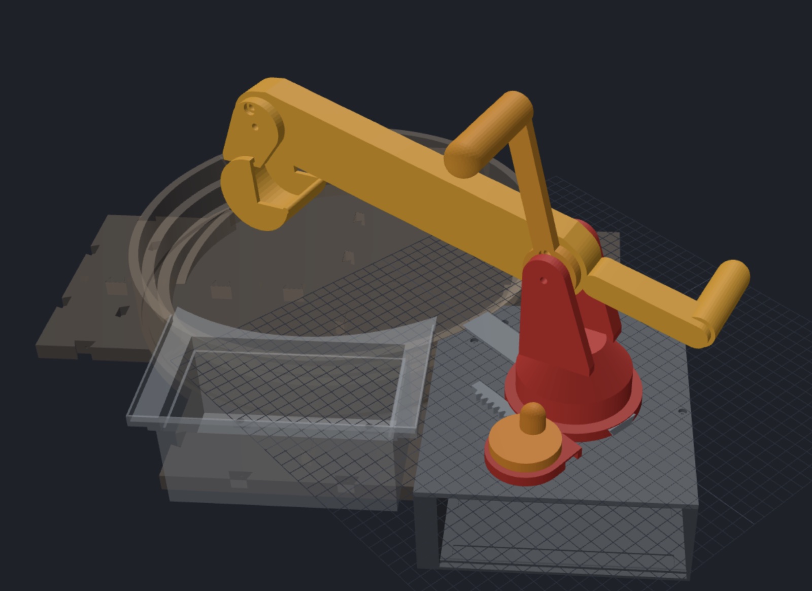
I wasn't going to print an arm to find out. Bench already has Dig Pod 1's parts, so I made an experiment, Dig Pod 3, and had Claude build the arm with a lead-screw cylinder on each joint that I could move with sliders.
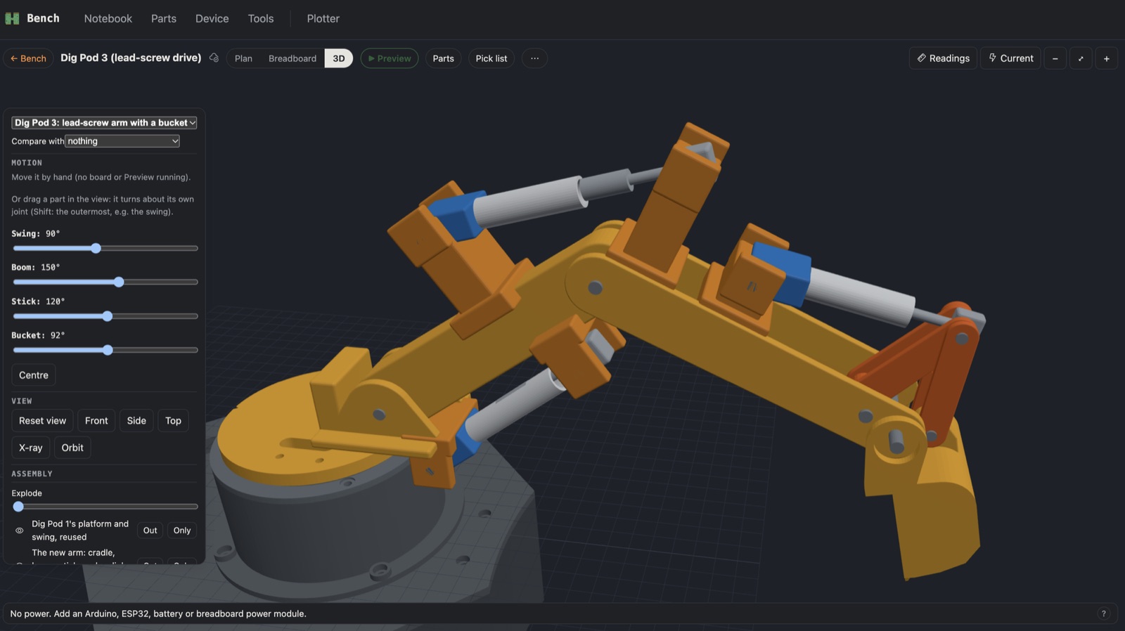
The first try reused Dig Pod 1's links and stood brackets on them. The cylinders worked and it looked like scaffolding.
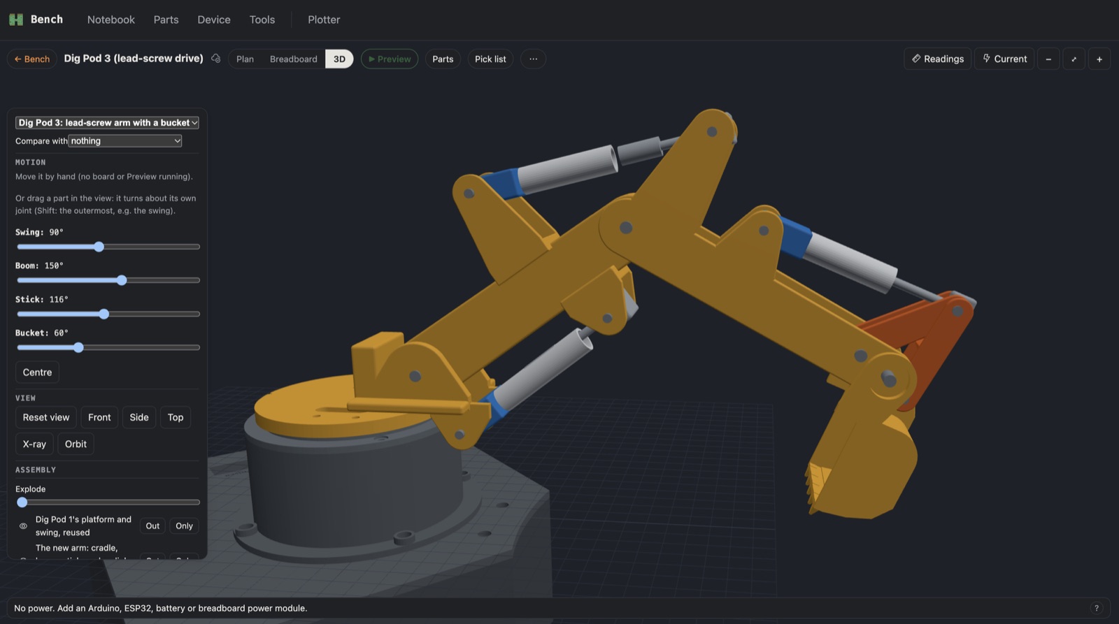
Next the mounts became part of the arm: gusseted ears in the plates themselves. This is also where I found parts floating. After I rounded every edge, pieces that only met at a flat face came apart. The script now checks that every part is one connected piece.
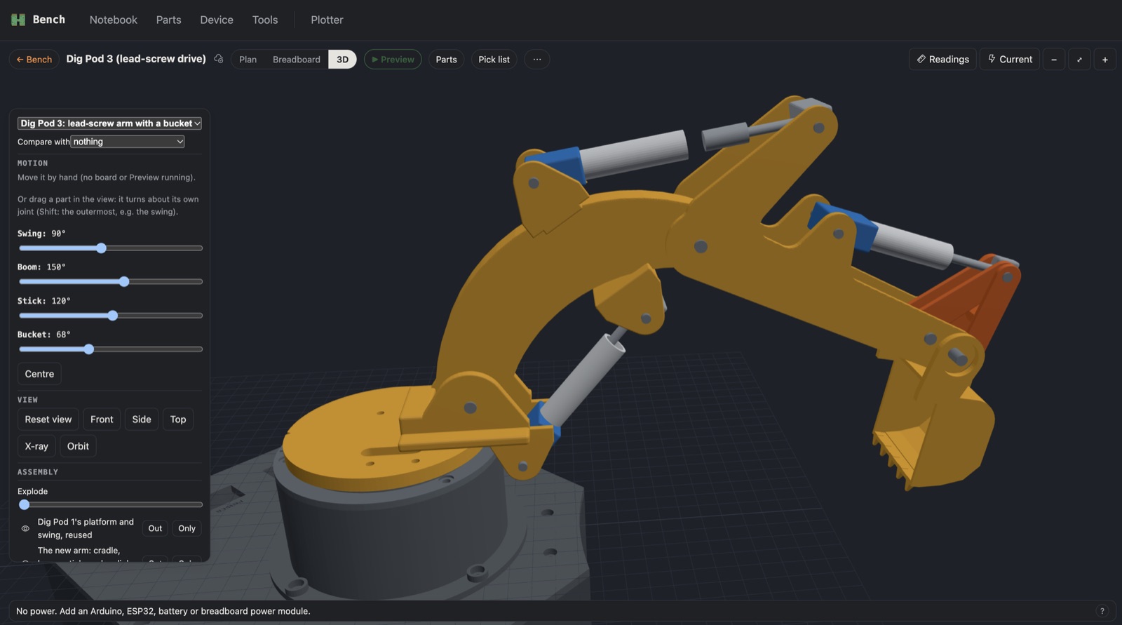
Then the shapes. I read a labelled photo of a real excavator and drew a big arch for the boom. It was wrong, and I said so. The real boom is only slightly curved, and the stick is one long plate whose top end protrudes past the boom's pivot as the lever the cylinder pushes. The picture at the top is the corrected version.
What the sandbox caught
The script moves the arm through eleven poses and reports any two parts that pass through each other. It found things I would have found with a roll of filament:
- The stick can't fold as far. Below 110° its top end swings into the boom, so the range dropped from 90 to 110.
- The stick cylinder's pin has to sit behind the pivot. Anywhere ahead of it, the pin swings down through the boom when the stick folds.
- The bucket's cylinder was too short. It couldn't hold its own servo and its stroke at the same time.
- A rod pulled out of its tube. I thought it was the animation. It was the sliders: they still allowed the old design ranges, past where the cylinders' fits were built to hold.
The bucket got its own lesson. I drew a new one and it looked blocky and unusable, and I said Dig Pod 1's bucket was perfect. It is. The linkage now hangs on that bucket with one small lug added to its back.
What I learned
- A model that moves finds problems a picture hides. Every collision above showed up only at a certain pose.
- Real machines carry the geometry. My arch was a guess. The photo had the answer.
- Tell the viewer what the model can't do. The 3D view only turns parts, so I had to measure how far the tube and rod drift apart (up to 4 mm) and cap the sliders at the ranges that hold.
- The savings are a hypothesis. A screw that holds for free is physics. Whether an SG90 can push my joints' loads is not yet checked.
Where it stands
The model has strokes of 40 mm on the boom, 29 on the stick and 22.5 on the bucket, which turns the bucket 106°. Nothing is printed. Next I want to run the force check: can an SG90 on a screw push each joint's load at those strokes? After that I'll modify one SG90 to continuous rotation (the dead one from the stick will do) and measure how fast it turns a screw and what it draws holding a load. Then I'll know if the idea saves anything.
Comments (0)