I spent days printing a bring-up board on the Snapmaker, and then the first servo wouldn't go in. The MG996R has a bump where its lead leaves the case, and I'd made a cradle that a servo has to be lowered into from above. The bump hit the wall on the way down. "Every mistake costs hours," I told Claude. This one cost days.
The bump
The bring-up board is meant to test Dig Pod 1's electronics before the pod's own parts exist. I'd already given Claude measurements for every servo. The MG996R's bump is 6.0 mm wide and sticks out 3.59 mm, and its top is 11.2 mm above the plate. The cradle I got had a cable window that stopped at 10.5. So the servo went down, the bump met the wall 0.7 mm too low, and that was that.
"I already provided extensive measurements for these servos," I said, and I had. The cradle came from the design in the servo-cradles kit, not from my measured lead. The model checked that nothing overlapped. It never lowered a servo into its seat.
A first fix raised the window to the bump's top plus 1 mm. It still didn't work, because the wall above the window was closed, so there was still no way to lower the servo past it. That's when I wrote what turned out to be the right answer: the wall needs 6 mm of clearance, so print a box with alignment slots and a cap I can glue on with CA. The new cradle has a slot all the way up the shaft-end wall, the bump's width plus 6 mm (12 mm for the MG996R), with a cap that sits in a rebate across the top. The check now lowers each servo from 40 mm above, bump and lead included. The old cradle hit it, from 2 mm to 22 mm above the seat. The new one drops clean.
Is this worth doing?
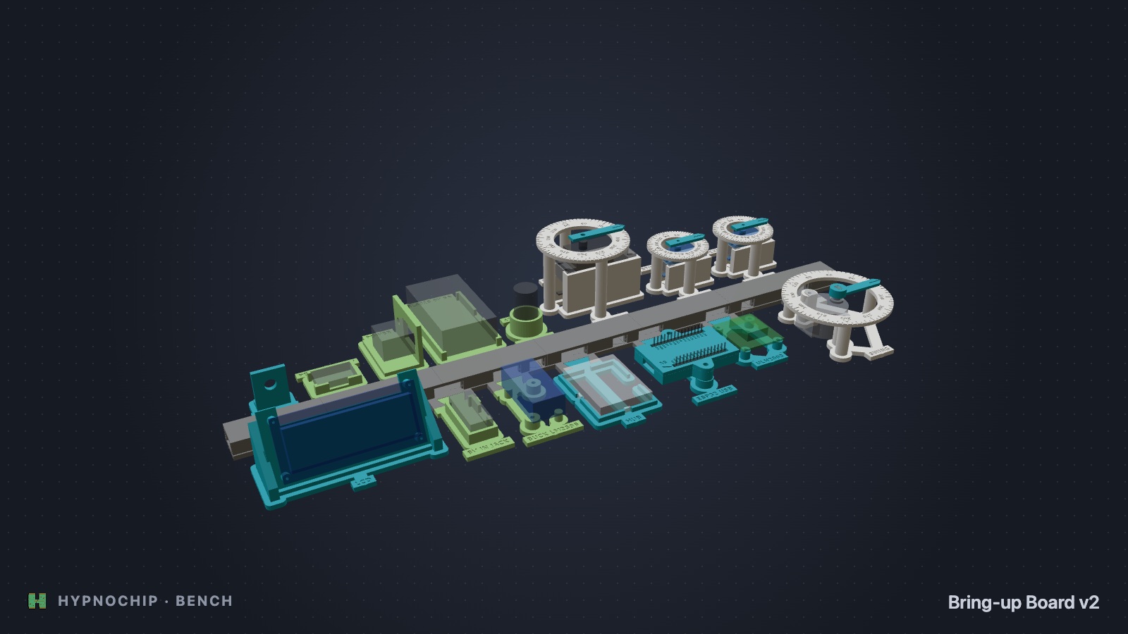
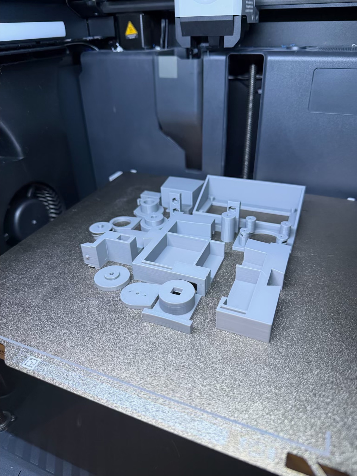
I'd had enough. I asked whether it would be quicker to print the real pod and its console and put it all together. Claude said yes, and I still wanted the board, but as a sequence I could bring up one device at a time. So v2 has no base plate, one small module per device, and a cable spine they all stand along. A wrong fit costs one module, not a six-hour tile.
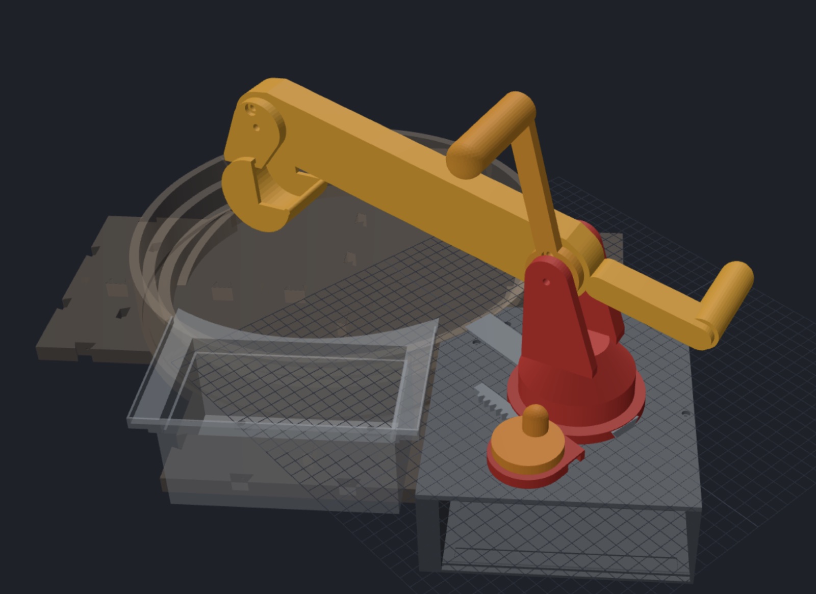
Before building it, I asked Claude to run the same drop-in test on the real pod. It found the same mistake. The boom's MG996R couldn't be installed in the pod's own cradle: its spline boss passes through a closed hole in the wall while its tabs sit on the plate. It neither drops in nor lifts out. A 13 mm slot through the top of that wall fixes it, and the pod's file is rebuilt.
I'd have found that one with the first real pod, in the assembly, with everything printed. The check is now a rule in my standards file: check every part can be installed, not just that nothing overlaps.
Where it is now
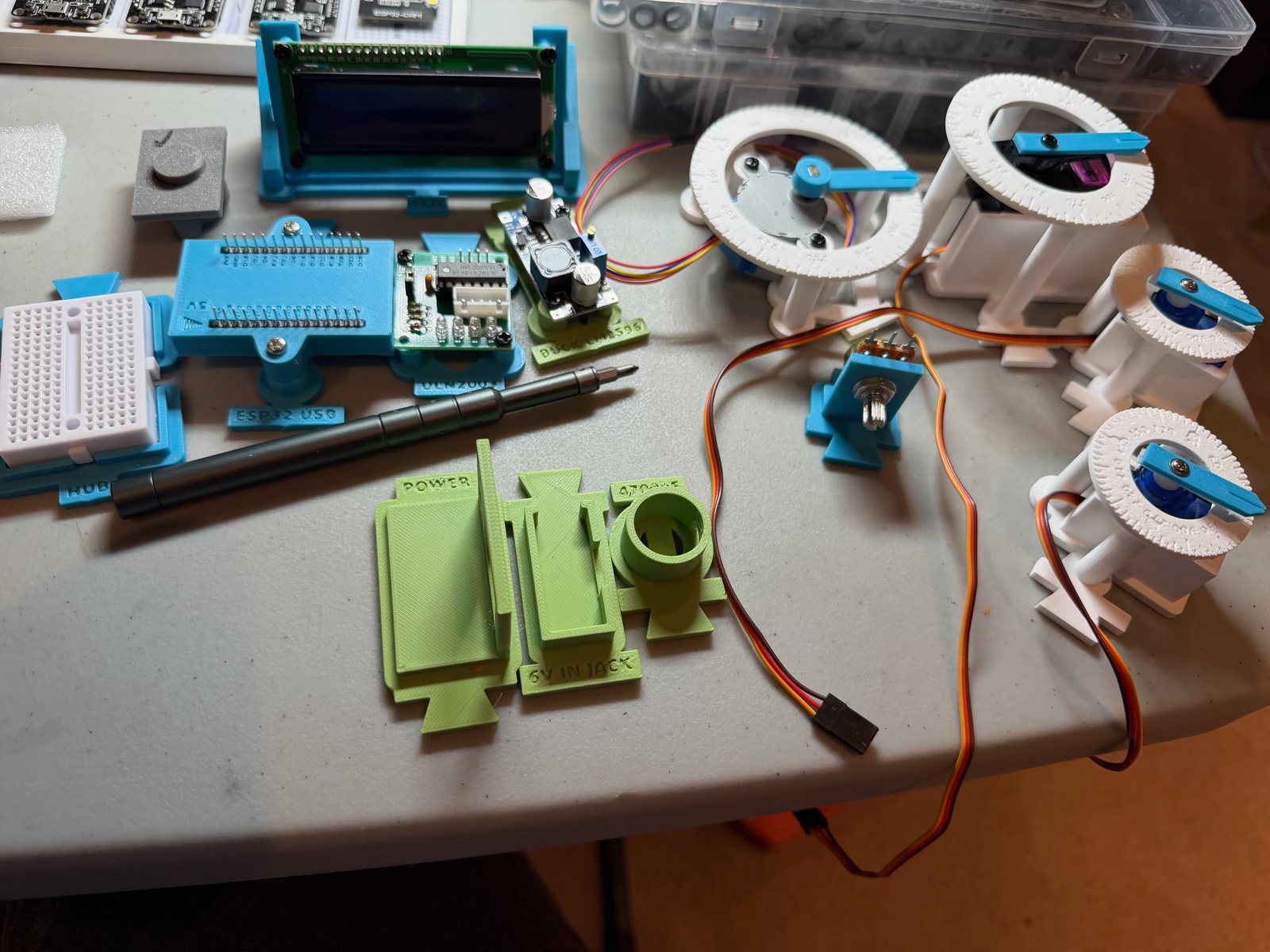
The modules are printed. The servos are in their cradles with the dials and pointers on, and the hub, the ESP32 carrier, the buck, the ULN2003, the LCD and the green power modules are done. The grey spine is the last plate on the printer.
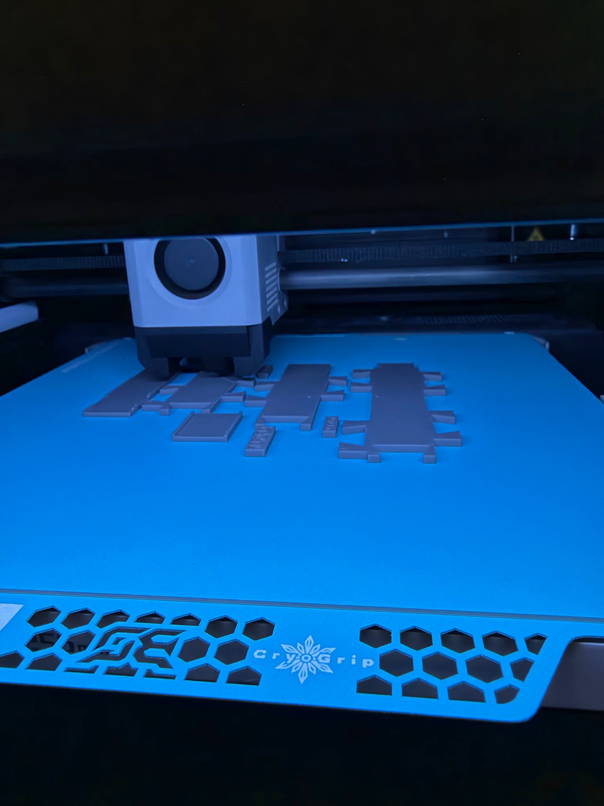
I don't yet know whether the glued caps will hold the servos firmly, or whether the channel caps will snap on. The spine and the caps are the parts I haven't been able to fit-test, so those are what I'm watching for.
Comments (0)