Result. I printed version 3 of the soaker's outdoor box and learned what was wrong with it by holding it. Version 4 answers each problem: the inside is now a sled you build at the bench and slide in, there's a basement for the cables, it prints without supports, the valve hangs from its own mounting bosses, and there's a mini PIR in the front. It isn't printed yet.
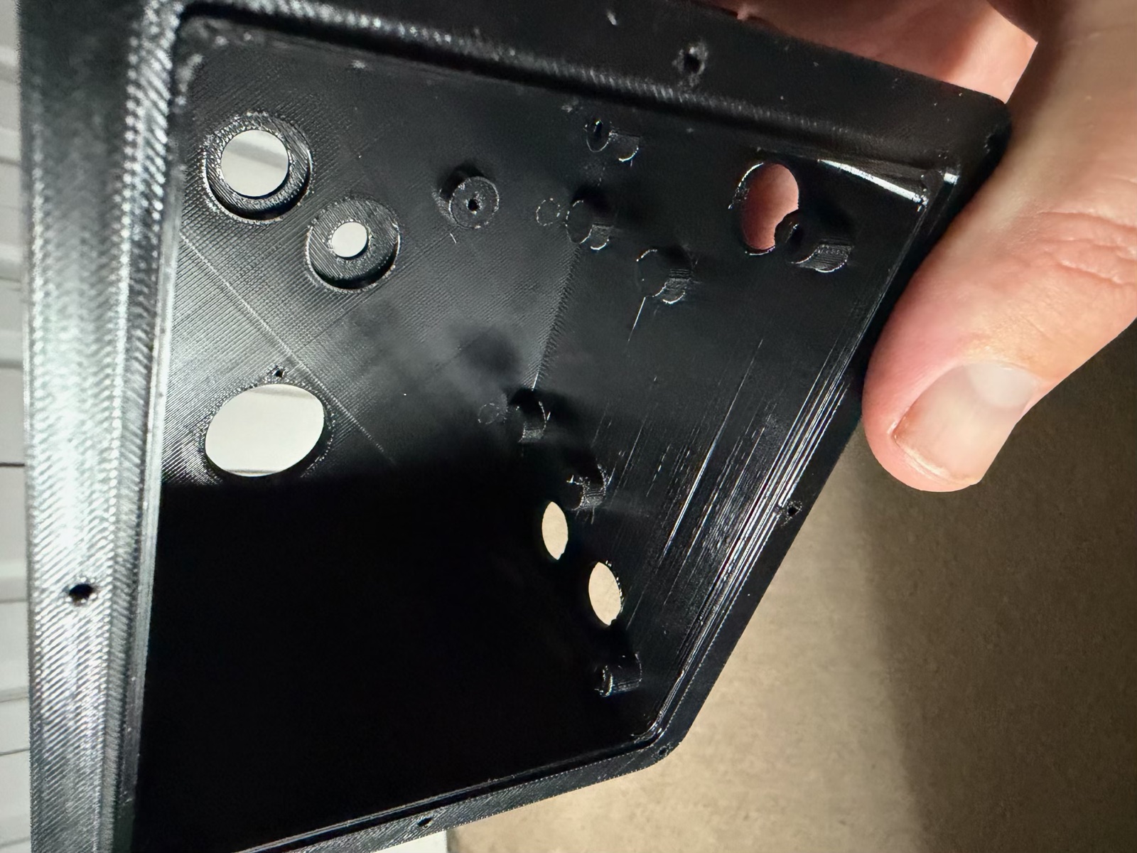
What the v3 print taught me
The v3 box body is the biggest print in the project. Holding it made three things obvious:
- I couldn't reach the screws. The tray's four screws, the camera carrier's two and the PIR's two were all deep inside a box I could only get a hand into from the back.
- The cables had nowhere to go. The cable glands come up through the floor, and the tray sat right on top of them.
- The valve cradle was the wrong size and hard to fit. Its four screws went up through 27 mm deep pockets, with the valve in the way.
A sled, like a drawer
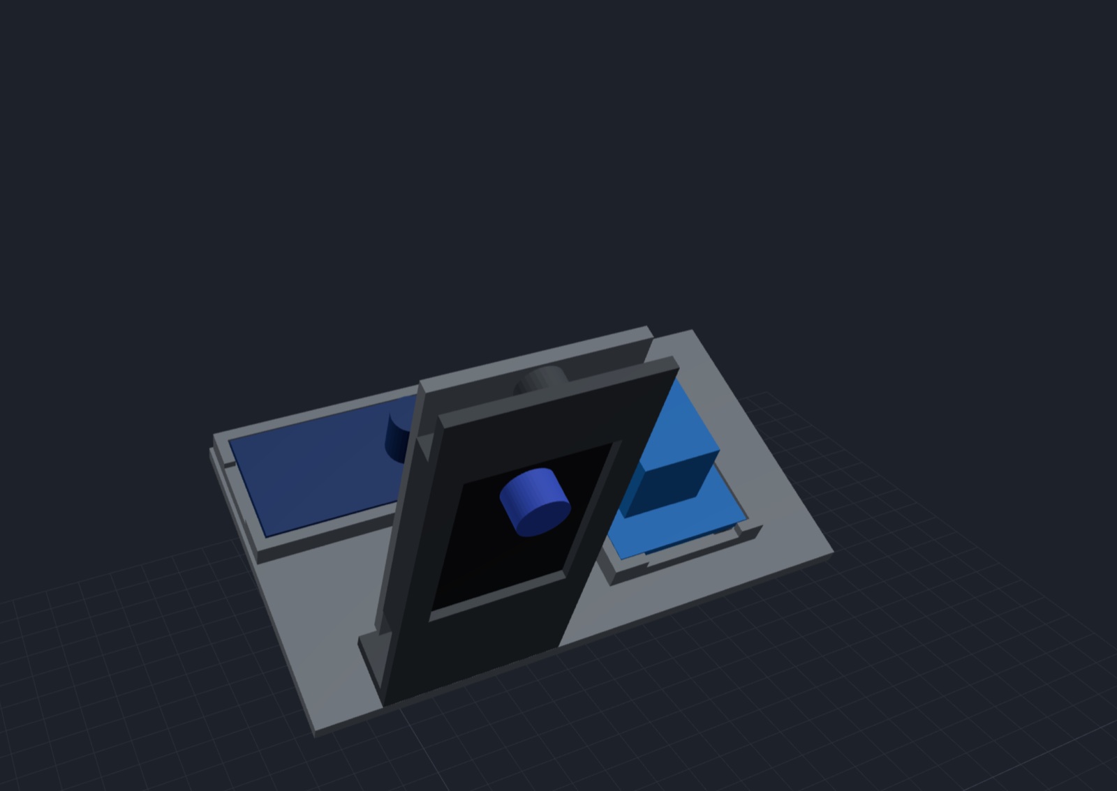
Everything inside now sits on a sled: the relay, the 12 V to 5 V buck converter, and the ESP32-CAM in its carrier and cover. I build all of that at the bench, where every screw is easy to reach. Then it slides into the box from the back on two ledges, like a drawer. The camera carrier stops on two pads behind the windows. The box tilts down toward the steps, so the sled stays pressed against them. Two screws go in horizontally at the back opening, a few millimetres in. No screw inside the box is driven vertically or reached for from deep inside.
I made the box 19 mm taller to give the sled a cable basement. The sled now rides 26 mm above the floor. The cables come up through the glands and have room to bend in under it, then come up through a slot between the relay and the buck. A check in the model script slides the loaded sled in from 80 mm out, over the cables, and makes sure nothing catches.
Printing it without supports
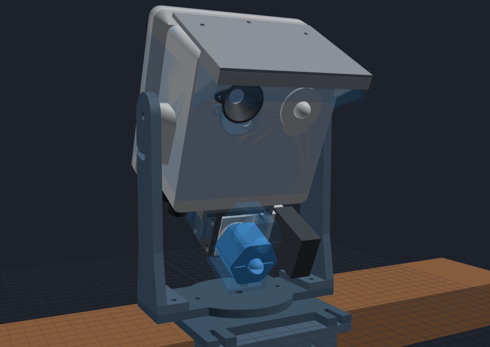
The box prints front face down, so anything sticking out of the walls has to build up from below. The first sled had two tabs 26 mm tall hanging under it, and the box had two tall fins to screw them to. Both would have needed supports. Now:
- the tabs are two small separate L-brackets
- the fins are short bosses with 45° fronts
- the bosses for the yoke's pivot lean forward at 45°
The model script now measures how much of the box hangs out past 45° in its print orientation. That went from 1,724 mm² to about 510, and what's left is round holes and bosses that print fine.
The valve, on its own bosses
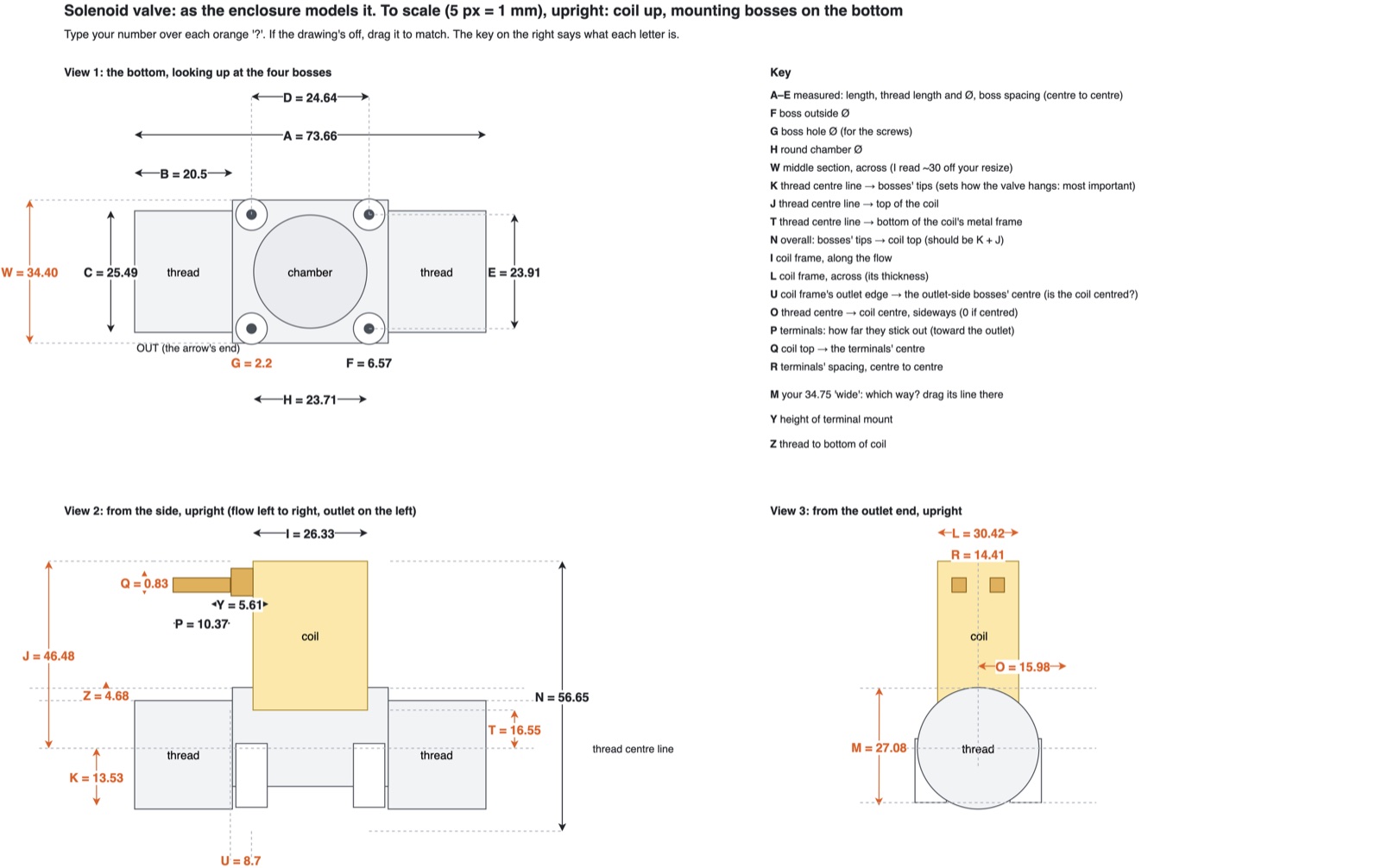
The valve turned out to have four mounting bosses on its bottom (finding out took a whole post: measuring the valve). So the cradle became two small parts:
- a hanger that screws to the same four holes in the box's floor, so it fits the v3 box I already printed
- an L-bracket that the valve screws to sideways, which slides into the hanger from the front
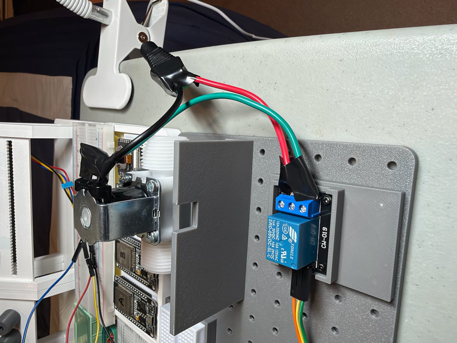
The valve lies on its side with the coil pointing out to the right. That keeps it to about 42 mm under the box, where pointing the coil down had it hanging over 60. Putting the real coil in the model found it sitting under one of the cable glands, so that gland moved to the other side. On the v3 box that hole gets a blanking plug.
Then I moved the relay to the right as well, next to the valve's terminals and the valve cable's gland. The buck converter went to the left, where the 12 V comes in.
A mini PIR
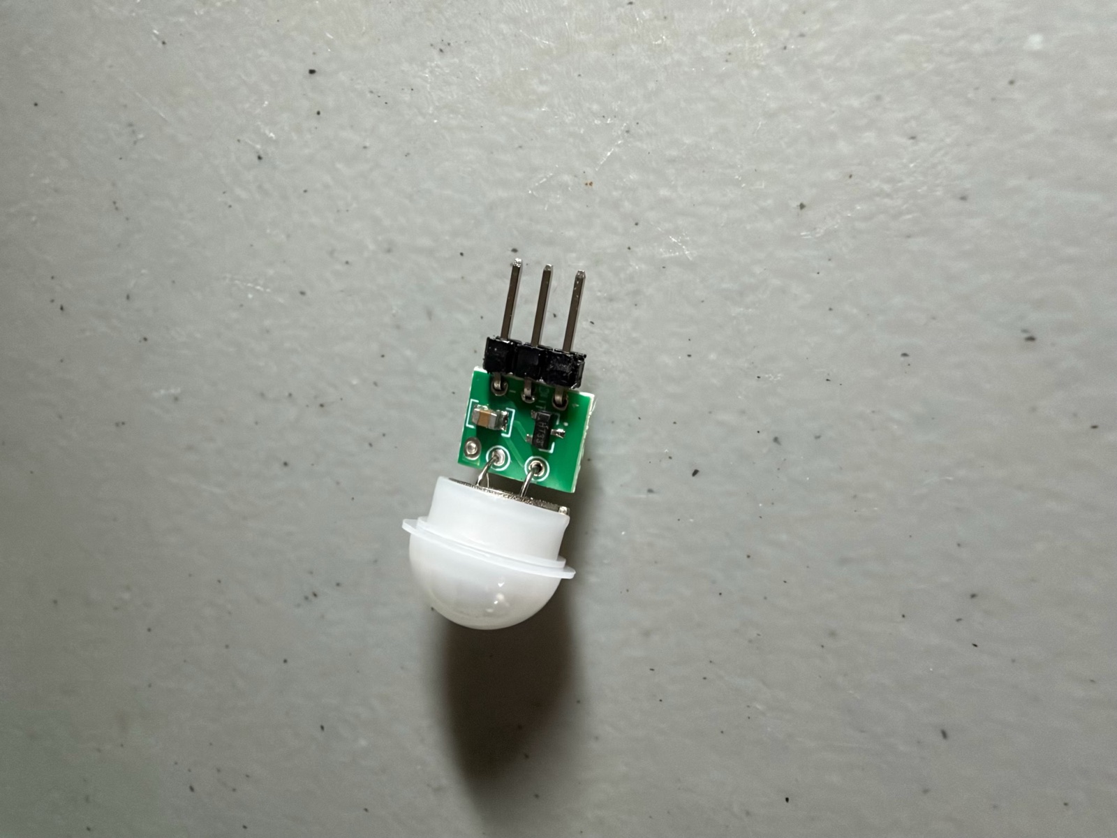
The camera can't see in the dark, so I bought an AM312 mini PIR. It runs on 3.3 V, which the ESP32-CAM has, and its output goes straight to a GPIO pin. It sits in a printed bezel that plugs the box's old PIR hole from outside, sealed with silicone. That's again no screws inside, and it fits the v3 box too.
The firmware reads it on GPIO 14, and there's a new setting for what sets off a spray:
| Setting | Sprays when |
|---|---|
| camera | the camera sees enough movement (as before) |
| both | the camera sees movement and the PIR saw something in the last 3 s: fewer false sprays from shadows and wind |
| either | the camera, or the PIR alone: for night |
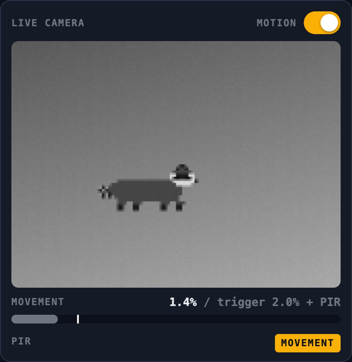
To test it before wiring anything, the stand-in camera in Bench's Preview (the 8-bit raccoon that walks past every 45 seconds) now counts as warm: while it walks, GPIO 14 reads high. With the camera's trigger set to 30 % so it couldn't fire, the raccoon set off a spray through the PIR alone: "PIR (the camera saw 0.7 %)".
One open question from the photo: the dome has a rim around its base that the listing didn't show. If it's wider than the bezel's 12.4 mm bore, it'll sit on the face instead of the shoulder. That's fine, just 1 or 2 mm further forward.
What's next
- Print the small front test piece first: the window and PIR area of the box's front, so the fits can be checked before the 185 cm³ box body.
- Wire the PIR, with a 100 nF capacitor across its power pins against Wi-Fi false triggers, and flash the board.
- Then water, finally.
What I learned
- Print the big part once, then design around what you couldn't reach. v3's box told me more in five minutes than the model had in a day.
- Build it outside the box. A sled you assemble at the bench beats any amount of clever screw access.
- Give cables room. A gland needs space above it for the cable to bend, not just a hole.
- Count the overhang. A number in the script catches what a glance at the model doesn't.
Comments (0)