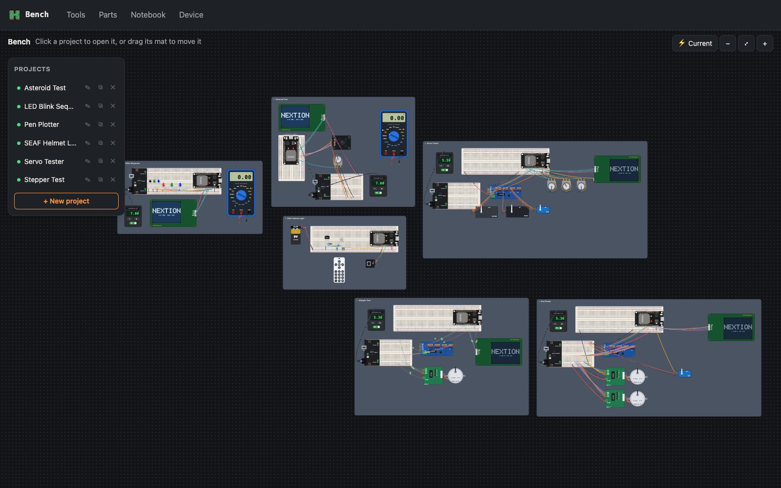
Result. In a week, Bench has grown from an Ohm's law calculator into the place where every project lives twice: on a canvas that simulates the circuit, and on the desk where I build it for real. The same sketch runs in three places: previewed on the Mac against the canvas, flashed to a real ESP32 from the app, and mirrored back onto the canvas while the real board runs. Six projects so far, from a blinking LED to a pen plotter.
One project, five views
Each project is one file. The views below are all drawn from it, so they can't disagree with each other.
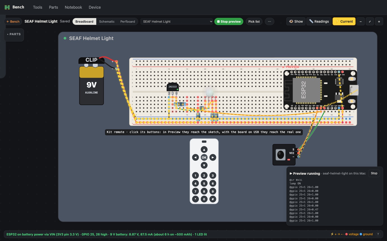
Breadboard: how it's built. Parts and jumpers sit in real holes, laid out the way they are on my desk. A circuit solver runs all the time: the status bar says what each supply is doing, hovering a pin shows its voltage, and ⚡ Current animates current from + to −. Below, the SEAF helmet lamp is switched on with the canvas remote (in Preview): 87.5 mA from the 9 V battery, about 6 hours. Off, it draws 39.7 mA, about 13 hours.
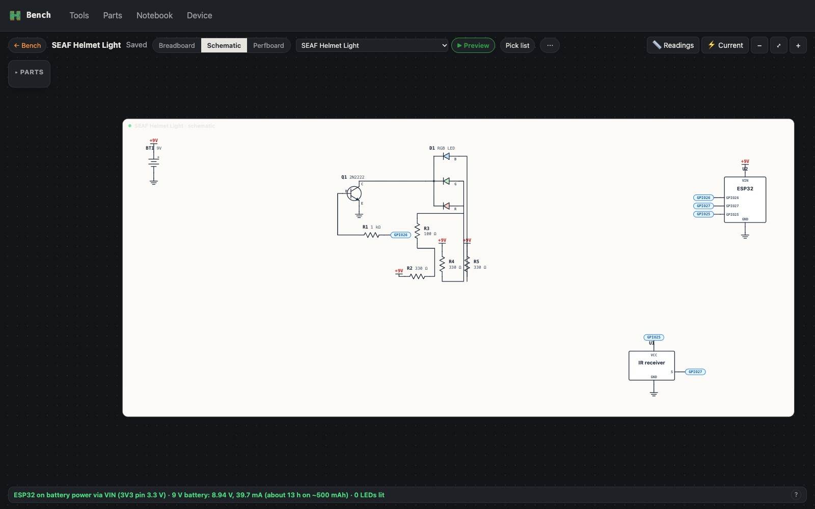
Schematic: how it's drawn on paper. Worked out from the breadboard. Parts get reference numbers (R1, Q1, D1), supplies become +9V and ground symbols, and wires to the ESP32 become labels like GPIO26.
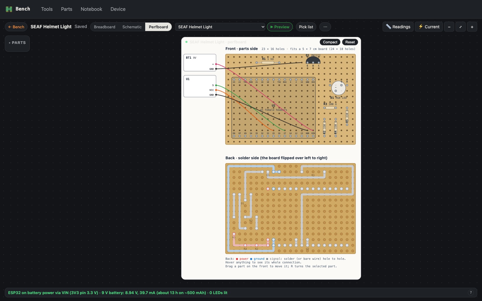
Perfboard: how I'd solder it for keeps. Front and back, with the back mirrored the way it looks when you flip the board over. Compact packed the SEAF lamp from a 60 × 17 breadboard footprint down to 23 × 16 holes, which fits a 5 × 7 cm board.
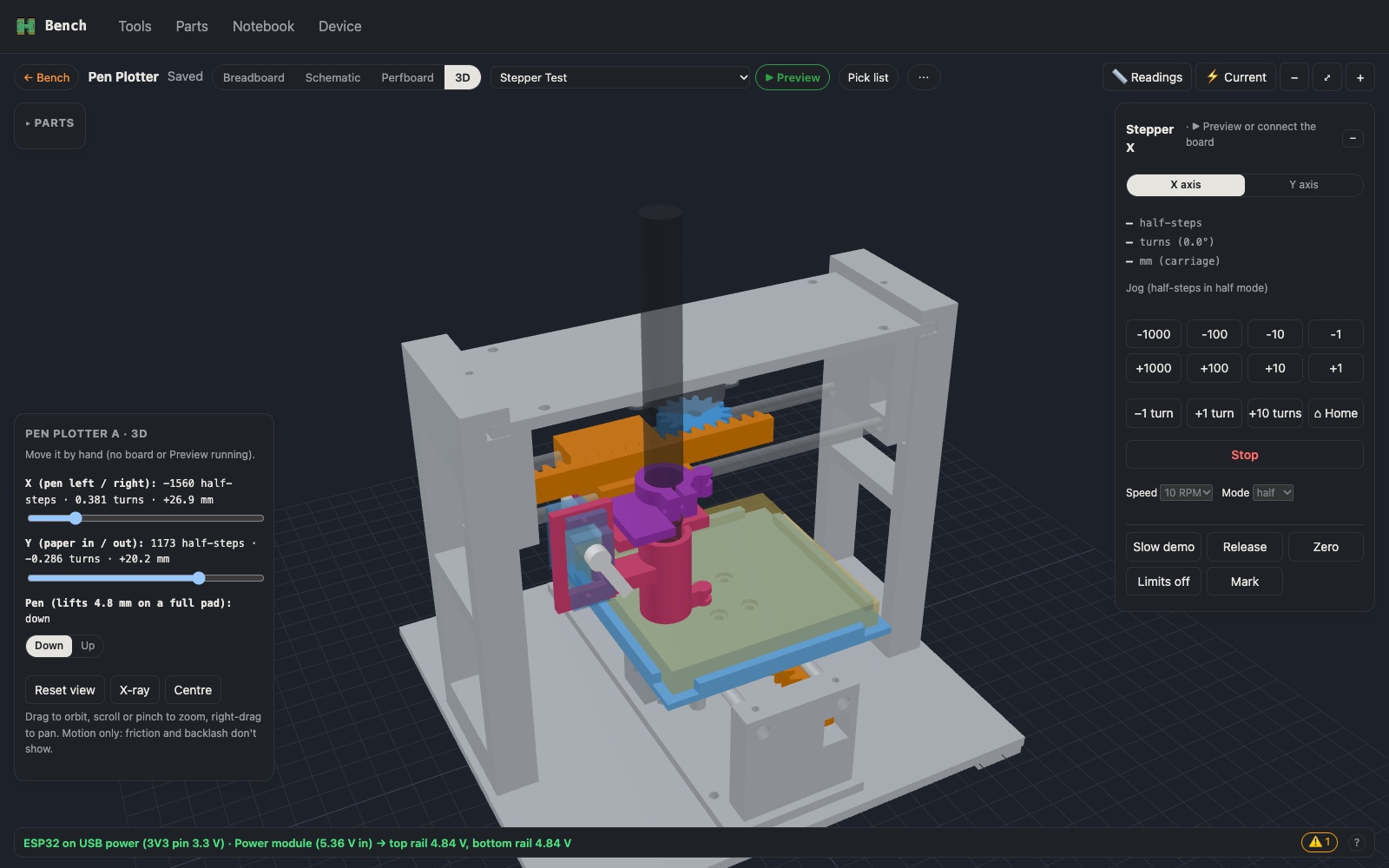
3D: the printed mechanism. For projects with printed parts. The pen plotter's frame, both axes, the pen holder and servo move with sliders, or follow the real board's stepper positions. The parts are Python scripts that write STL files, checked for collisions at every corner of travel before I print.
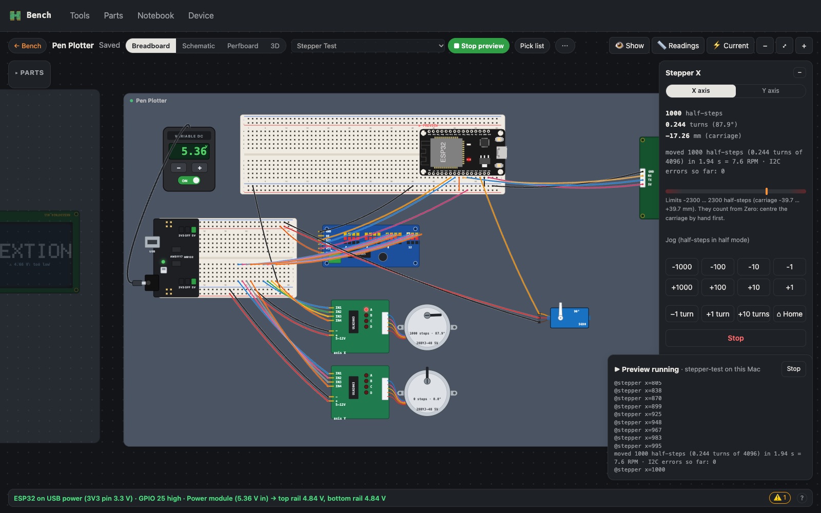
The sketch: how it behaves. ▶ Preview compiles the project's ESP32 sketch on the Mac and runs it against the canvas: its pins drive the simulated circuit, the Nextion display is emulated, and the canvas remote, knobs and buttons feed it input. Below, the stepper test is jogging the X motor 1000 half-steps: the motor's dial turns and its ULN2003 LEDs follow.
From the canvas to the desk
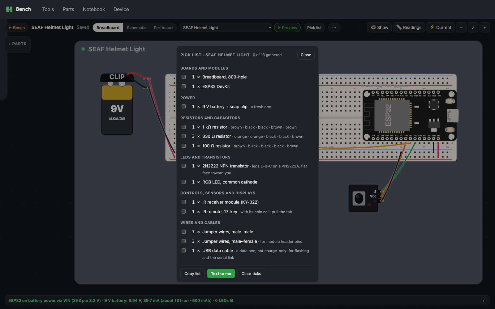
- Pick list. Every part to gather, counted and grouped: resistor colour bands, the transistor's leg order, jumpers by type (male–female where they meet a module's header). Tick them off as I go, or text it to my phone.
- Wiring checklist. Right-click a jumper on the canvas when it's in on the real breadboard: it fades with a ✓, and the Show button counts "18/22 wired". Show / hide hides parts and their wires while I build one section at a time.
- Flash from the app. The Device page builds and uploads to the ESP32 over USB. All my ESP32 DevKits look the same to the Mac, so Bench reads each board's start-up line to tell me which sketch is on it, and warns me if it isn't the project's.
- Live mirroring. While the real board runs, its serial lines (
@gpio,@servo,@stepper…) drive the canvas: LEDs, servos, steppers and the 3D model move with the real hardware. - Panels for the job. A Servo tester with sliders and min / centre / max marks for each channel; a Stepper panel with jogging, X / Y axes, Home, soft limits and a Mark for measuring backlash.
- Readings. My meter readings and caliper measurements are saved with each project, and Copy as a table pastes them into an entry like this one.
- Every display sketch starts with the Hypnochip splash for 4 seconds.
Numbers it helped me find
| What | Measured |
|---|---|
| 28BYJ-48 half-steps per turn | 4096 (exactly 64:1; 10 turns stopped ~1° past the mark) |
| Test axis travel | 69.92 mm per turn, 17.07 µm per half-step |
| Test axis backlash | ≈ 0.01 mm |
| MB102 regulator | 5.36 V in → 4.84 V out (needs 6–7 V in under load) |
| SEAF lamp, 9 V battery | 39.7 mA off (~13 h), 87.5 mA on (~6 h) |
| Sharpie Fine Point | front 10.6 mm, body 11.98 mm from 36.95 mm above the tip |
What I learned
- One source of truth. Because breadboard, schematic, perfboard and sketch all come from the same project, fixing a wire fixes it everywhere.
- Simulate first, then build. Preview catches sketch mistakes before anything is flashed, and the solver catches a short or a burnt LED before it happens on the desk.
- The canvas has to match the desk. The models are calibrated to my real readings (the MB102's drop, the joystick's 1880 centre, the motors' 4096 steps), so when the canvas and the bench disagree, something is wired wrong.
- Readings beat guesses. Every hardware problem this week was solved by a meter reading at a specific point, not by swapping parts at random.
- Check strength, not just fit. The first pen plotter frame passed every collision check and still snapped: one post was 1.5 mm thick. Now the model checks wall thickness too, and the legs print lying down.
Comments (0)